Notice
If you get a question wrong, you can still click on the other answers. This will open up hints and explanations (if available), which will provide additional information.Disclaimer: While every reasonable effort is made to ensure that the information provided is accurate, no guarantees for the currency or accuracy of information are made. It takes several proofreadings and rewrites to bring the quiz to an exceptional level. If you find an error, please contact me as soon as possible. Please indicate the question ID-Number or description because server may randomize the questions and answers.
Go to: Midterm Exam
Geology (GLGY 341-UCAL) Final Exam
Congratulations - you have completed Geology (GLGY 341-UCAL) Final Exam.
You scored %%SCORE%% out of %%TOTAL%%.
Your performance has been rated as %%RATING%%
Credits: Based on the excellent class notes provided by, Dr. Bernard Guest during Winter 2013.
FAQ | Report an Error
Information is provided “as it is” and sanuja.com takes NO responsibility for the accuracy.
5 point questions: Contrasting two concepts
Andersonian and non-Andersonian deformation
In Andersonian faults, both maximum and minimum principal stresses are horizontal or tangential to the earth’s surface and intermediate principal stress vertical and therefore, no appreciable extension or shortening of the earth’s crust and transcurrent faults or strike-slip faults are generated. The angle of the propagating fault and the normal in Andersonian is about 60-degrees(normal fault). Non-Andersonian faults are characterized by non-horizontal or tangential forces acting on a block causing the material to expand.
Also, in Anderson’s classification, we assume that one of the principle stresses is vertical and strain is coaxial.
Stress and Strain
Stress is the force that acts on a body, therefore it is defined as the force applied over an area. The Strain is the resulting deformation caused by the stress. Strain changes the geometry of an object. When the stress exceed the material stength, it will result in strain.
Coaxial and noncoaxial
Coaxial deformation will keep the principle elongation axis of the strained body in the same orientation. The special type of which known as, uniaxial contraction strain involves the reduction of volume through reorganization of porous rocks leading to a denser more packed materials. This type of contraction will result in dissolution of grains and minerals. The uniaxial extension will result in increase in porous space and is accommodated by tensile fractures or veins. In the coaxial deformation, the shorting of a one axis corresponds to the elongation of the other. For example, shorten vertically will result in elongation horizontally. The fundamental strain lines will always remain perpendicular to each other.
Noncoaxial strain occur when a horizontal force (shear) is applied to a material. It will change the length of sides while the orientation and magnitude of the horizontal axis will remains the same. Simple shear is a good example of a non-coaxial strain.
Distortion and translation
Distortion refers to change in shape of an object through either coaxial or non-coazial deformation (or a combination). Translation also a rigid body deformation in which the entire rock volume changes its position, where every particle moves in the same direction and travels the same distance. Translation requires no changes to the principle elongation axis (no change in shape).
Simple shear and Pure Shear
Pure shear will result in change in length of the strain ellipse, but it will conserve the orientation of the axis. Simple shear will result in change of both the orientation and the length of the strain ellipse. Since shear is measured using the deflection of originally vertical lines on a body, you could say that pure shear has no shear component (but don’t write this on the exam since it is my logical argument; LOL).
Differential stress and deviatoric stress
The differential stress is the difference between the maximum and minimum principle stresses experienced by an object. In Mohr space, it is the diameter of the circle. Deviatoric stress is the deviation of the principle stress axis from the normal because the solids can sustain shear stresses. In Mohr space, it is the radius of the circle.
Shear stress and Normal stress
The Shear stress will result in change in the orientation of axis while normal stress will not. Shear stress is parallel to the surface of the object while the normal stress is perpendicular to the surface of the object. In other words, all surfaces directly perpendicular to the principle stress direction will experience the maximum normal stress with no shear component (zero). Also read, Simple shear and Pure Shear
Rotation and Translation
During rotation, the entire rock volume moves along about a vertical axis (plate motion, India for example) or horizontal axis (tilting of a block). In rotations, usually the particles will move in a circular path. It is possible that the entire rigid body has rotated as opposed to grain rotation. Translation will move each and every particle in the same direction with the same distance. Check this image-click here
Stress ellipse and Strain ellipse
Stress ellipse describes the forces per unit area applied to a body. The longer axis of the stress ellipse experience the highest principle force. Strain ellipse is the preserved history of the stress event. The longer axis of this has experienced the lowest stress (force per unit area). It describes the amount of elongation in any direction (deformation), therefore represents the deformed state of an unreformed material.
Elastic and Plastic behaviors
Elastic deformation occurs when the tensile strength of a rock is strong enough to overcome the forces applied. As long as the rock behave as an elastic material, it most likely have the ability to restore itself to the original unreformed shape. However, if the forces overcome the strength of the material, it will result in plastic deformation, where the fractures could propagate (and the rock loses its ability to come back to the original shape).
Lithostatic and Hydrostatic
They are similar to each other. Lithostatic pressure is caused by the surrounding rocks and materials applying a force on an object. They do not have a shear component since the the forces are acting on each other at almost or at equal magnitude. This behavior is observed in hydrostatic pressure situations where the pressure in a liquid is equally spread out around a given volume. In both cases, pressure increases with the depth.
Cataclasis and Coble Creep
Cataclasis is caused by inter-granular and intro-granular fracturing, sliding and grain rotation. Deeper deformation involves spallirity of flanking and trans granular fracturing.
Coble creep is caused by migration of vacancies in the crystallographuuc lattice. Diffusion through x-tails is called volume or Nabarro-Herring diffusion. Diffusion along grain boundaries called grain boundary diffusion or coble creep. It is a type of plastic deformation mechanism.
Pseudotachylite and fault gouge
Pseudotachylites form along the fault surfaces due to frictional melting (or flash melting) of the rock bodies within the fault zone. It is cohesive glassy or very fined grained and unbrecciated. Fault gouge is characterized by the brecciated fault rocks between the blocks in the gouge zone. They are more common than pseudotachylites.
Mineral fibre lineations and Chatter marks
Minerals (and mineral aggregates) can form a linear fabric by recrystallization, dissolution-precipitation and/or rigid rotation. Aligned prismatic minerals such as amphiboles in amphibolite can be used to determine the history of a deformation. The elongation of the minerals are in the directions of least stress or the sigma-1 is perpendicular to the elongation. Chatter marks are linear features developed on an M-surface which used for identifying the movement of the fault.
Lineation on a slip surface often represent the last slip events, which may not be accurate. Therefore chatter marks are used to determine the slip vectors.
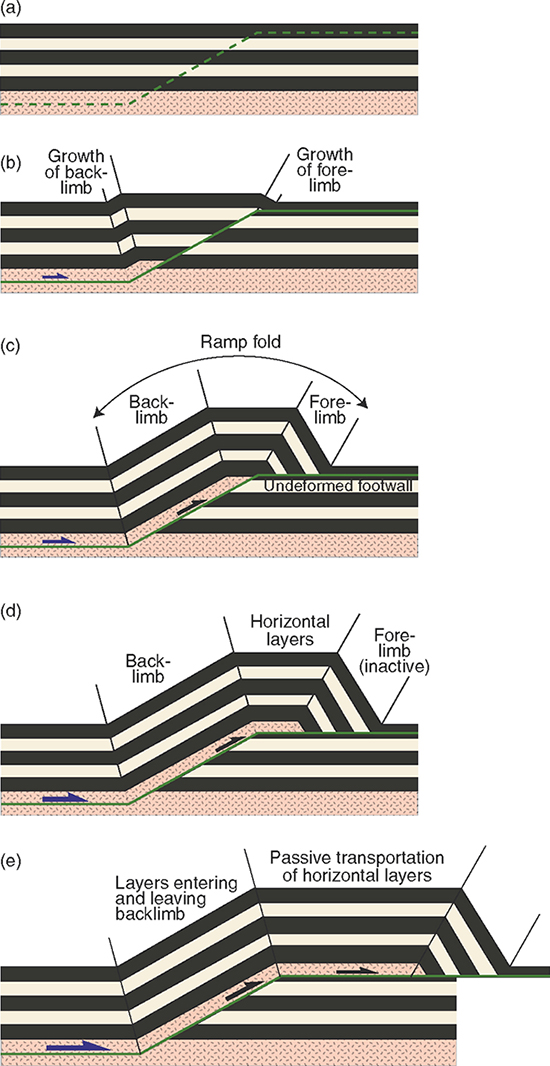
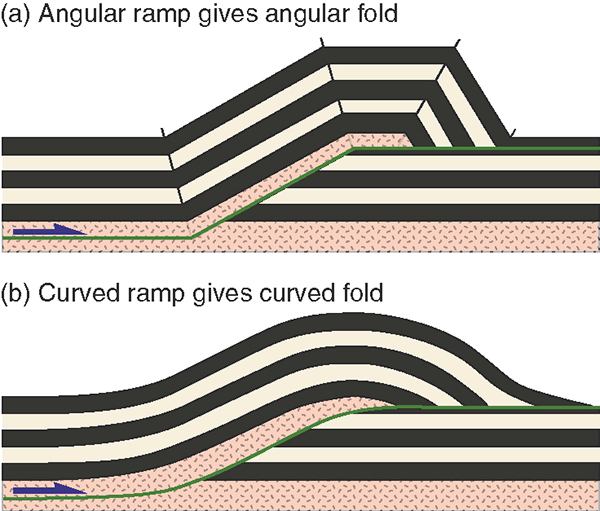
Fault Bend and Fault propagation folding
These form where a tectonic unit is passively transported over a ramp (“bend”) in its sole thrust. Fault propagation folds form above the tip line of a trust to accommodate the deformation in the wall rock around the tip.
Transpression vs transtension
Transpression is formed during collisions between plates at oblique or non-orthogonal subduction. It will create oblique thrust faults. Crenelation on rocks can be used to identify these. Transtension are caused by oblique tensional environments. Rifting events are the most common type of environment for this type of event.
Buckling vs. bending
Buckling and bending are similar in that they both involve bending moments. In bending these moments are substantially independent of the resulting deflections, whereas in buckling the moments and deflections are mutually inter-dependent – so moments, deflections and stresses are not proportional to loads. (NOT sure about this answer, since I can’t seems to find it in notes) These will occur in areas of reverse and trust faults.
Another way to describe the difference; buckling will produce periodic waves of deformation, when the compression force is horizontal (parallel) or near horizontal to the plain. It will always produce a wave like structures. Bending will not produce a wave like structures and the force is applied normal to the plain.
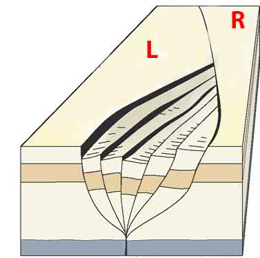
S tectonites vs. L tectonites
To put it simply, lineations (L-tectonites) are indications of constrictional strain and foliations (S-tectonites) are an indication of flattening strain. Planar (s) and linear (L) fabrics with preferred mineral orientations that penetrate rock from micron to cm scale. L-tectonics can be used to identify the orientation of primary stresses because they get deformed as it stretches as opposed to S-tectonics, which is being squished.
Orthogonal Flexure vs. flexural flow or slip.
Please read the article, Fold Geometry
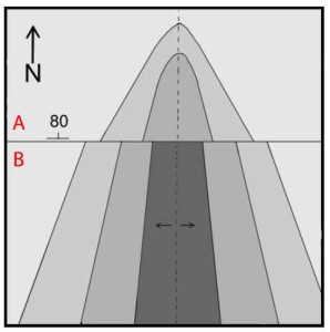
Poiseuille vs. Couette flow
Poiseuille flow occurs when salt flow into a diapir, following the path from high to low pressure. Fastest flow would occur in the middle of the diapir. Couette flow of salts occur when a layer of salt gets pushed as a result of surrounding block movement. The fastest flow rates can be found for later is near the moving block. Couette flow is similar to laminar shear (technically it is laminar shear kind of movement).
5 point questions: short conceptual questions
Describe joint surface anatomy
Joints are planar, through-going fractures usually caused by Mode 1 or pure tensile fractures. Their surfaces are typically elliptical and confined to a single layer of rock (terminating at the upper and lower bed surfaces). However, it is possible for joints to propagate if the lithology of the surrounding rocks are similar to each other. Ribs and hackles are observed on such surfaces.
Ribs are curved features that form along the tip of the propagating fracture. In other words, event of the growth of a fracture will form a rib. Plumes radiate outwards from the center cutting through the ribs, but still with a circular pattern. Hackles develop between the ribs as a result of twisting of the rock.
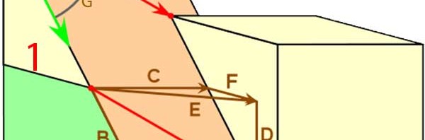
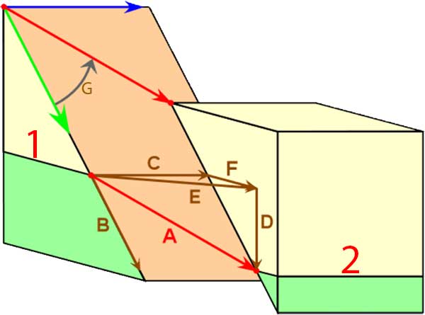
Explain the different component of slip for fault offsets.
Please read the following articles;
Stereographic Projection
Displacement Vectors
What are tension gashes and how are they useful?
They formed in the fault plane and useful for determining the orientation of principle stresses and the sense of movement. It usually form a “S” or “Z” shaped structures. On a vertical plain, if the gash is like and “S”, the top block is moving to the left. If the gash is like a backwards-S then the top block is moving to the right.
What is an “Andersonian normal fault”? Explain using Mohr and physical space diagrams.
Andersonian normal faults should form with about 60-degree dip on the physical space, but with a 120-degree angle between the sigma-1 and the fault surface. Also read, above…
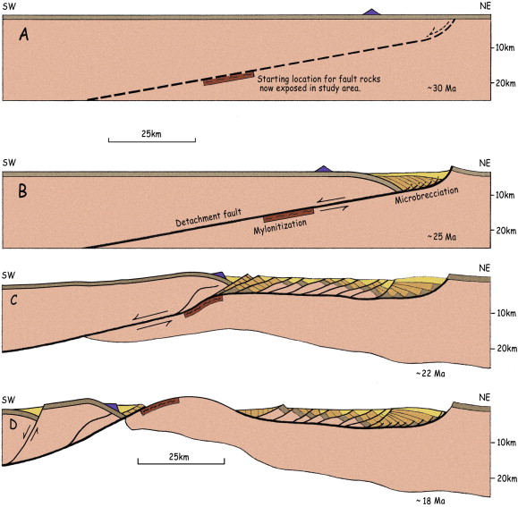
How does a metamorphic core complex evolve?
First, the metamorphic core complex is a term given to an area that has an exposed layer of deep crust due to exhumation. They are characterized by low angle faults, which usually not found in nature.
- Ductile shear zones undergo regional extension.
- Ductile zones creates horizontal horizons which changes the behavior of the propagating normal fault. This will result in low angle faults at the base of the weak horizon.
- Inversion (re-activation) of normal faults into a reverse fault due to compressional event.
- The load on the top of these inverted faults push the older deep sediments up on to the surface.
- Now if an extensional event occur, it will further uplift the older less dense crustal rocks on to the surface as a response to decrease in load.
1. Ductile shear zones undergo regional extension. A listric normal fault (low angle faults) forms in the upper crust flattening along a weak detachment zone near the brittle-plastic transition boundary.
2. Due to further extension, new faults form in the hanging wall at the same time the original fault is reactivated. This even cause the upper curst to be thinned.
3. The isotactic uplift bellow the thinned portion of the curst cause upward movement in the lower (Moho) crust. This causes the original fault to be rotated to the point where it becomes mechanically favorable to create a new fault in the hanging wall.
4. Process repeats until a series of rotated domino-style blocks and related half-grabens are created. The steepest fault is the youngest active fault.
5. During the repletion of the first four steps, the upper crust is continually thinned. In response, the buoyant Moho in the lower crust is uplifted.
6. Over time, erosion eventually reduce the upper hanging wall exposing the lower curst to the surface.
7. This lower exposed plate is known as the metamorphic core complex.
8. If a reversal of tectonic event occurred, the compressional forces will reactivate the primary fault(very first one) known as inversion, causing further uplift of the older Moho.
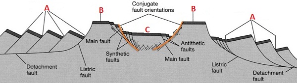
A. Half-grabens
B. Horst
C. Graben
In short, core-complex tectonite results from simple-shear rotational strain within regional ductile shear zones that have accommodated a Tertiary crustal stretching. Most are found where large extensional strains overprint contractional deformation such as an orogenic belt.
Draw a Duplex and label all of the elements.
Bended and stpover geometry in fault zones generates the strike-slip duplexes. Extensional duplexes form at the releasing bends while compressional duplexes from at the restraining bends. Extension will result in “dropping” faulted materials hence known as a negative flower structure (or tree). Compression will uplift materials in the bend, hence known as positive flower structure (or flower). Check this out!
Sequence thrusting often forms duplexes in regions of faults in the imbrication zones. Imbrication zones are regions with smaller reverse thrust that are oriented through a low angle flow thrust.
Draw a Fault bend fold and label all of the hanging wall and foot wall relations.
check under first few questions above…
Describe flexural slip folding and the small-scale structures you might expect to see in a flexural slip fold.
Explain how cleavage is used to orient one’s self relative to fold geometry.
Draw a diagram that explains how both extensional and contractional structures are related to a salt detachment
20 point questions
1. Stress
Check under five points questions
2. Strain
Check under five points questions
3. The Mohr diagram
4. Failure envelopes and their relation to strain.
On the right side of y-axis is the compressional regime and on the left side is the tensile regime. Depend on the type of material, experimentally we can determine the best type of failure envelope. The shear fracture condition for uniaxial compression is always falls on a tangent of the circle with failure envelope as the tangential line.
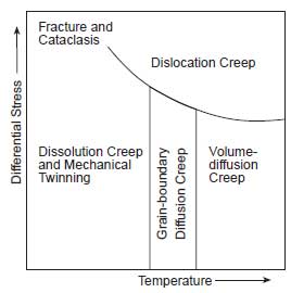
5. Deformation mechanisms
The mineralogy, temperature, confining pressure, fluid pressure, differential stress and strain are key factors that derive the deformation mechanisms in rocks. Following are few general types of mechanisms;
- Mircrofracturing, cataclasis, and frictional sliding: formation, lengthening and interconnecting of microcracks which result in frictional sliding along the cracks and grain boundaries.
- mechanical twining and kinking: less aggressive than above because strain is achieve by bending (not by breaking of the lattices)
- diffusion creep: changes the shape and type of crystals through the movement of vacancies and atoms within crystals and along grain boundaries.
- dissolution creep: changes the shape and size of crystals by dissolving materials.
The physical conditions which these types of mechanisms operates can be plotted on a graph of Temperature and Differential Stress, known as deformation map.
6. Explain joint propagation and spacing as well as joint face anatomy and relate this to stress.
Check under 5 points questions…
7. Explain Riedel and S-C fabrics and relate these to the stress field
- combination of foliation (S) and shear bands (C)
- oblique, transect each other
- can be used to determine strength of shear strain and sense of rotation
- used to identify if coaxial or coaxial
- related to mylonite; mylonites that show S-C structures are called S_C mylonites
- formed in a shear zone in a magmatic rock. S foliated are cut by shear surfaces (C). Continued deformation rotates S into close parallelism with C (CS foliation)
- use S bands to show evolution of shearing
8. Describe the features you would expect to see along a major dextral strike slip fault that includes a prominent right hand bend and a large left step over. Use fully labeled diagrams, and relate everything to a stress field.
9. Describe fold classification, including fold anatomy and the main classification schemes.
Please read the article, Fold Geometry
10. Explain what cleavage is, the different types and what controls cleavage orientation.
Both cleavage and foliation can be observed in the field. Do not get confused with mineral cleavage because rock cleavage responds to external forces vigorously. Temperature, pressure, lithology and mineralogy controls the cleavage formation. Cleavage is actually a low temperature version of foliation which is best developed in rocks with abundant platy minerals.
Cleavage is the ability of a rock to break along sub parallel surfaces. They generally found in low-grade metamorphic rocks. If they are spaced at a regular interval, they are called spaced cleavage. If the spacing is less than 1mm, it is called continuous cleavage. In general, they look like closely spaced, planar to curviplanar surfaces. And they are associated with folds such that they are oriented parallel to axial surface of folds. They are formed by grain rotation growth of minerals with preferred orientation and wet diffusion.
They are different types of cleavages. There are pencil cleavage, compaction cleavage, styolitic cleavage, slaty cleavage.
Compaction cleavage is formed by collapse of pore space and it is considered continuous cleavage. Styolitic cleavage forms by pressure dissolution along planar surface. It is a spaced cleavage. Pencil cleavage is formed when s0 is subparallel to sigma 1 and s1 forms at high angle to s0. The rock breaks break along s0 and s1 forms pencil shaped rod like structures. Slaty cleavage forms when s1 dominates the rock and obscures s0.
Most cleavages are axial plane and thus can be used to determine the deformation history of a rock. The orientation of the cleavage varies from layer to layer depends on the stresses acting on them. For example, the cleavages observed in folds changes orientation based on the relative position to the neutral points (forces are near zero). Tectonic forces causes foliations to form. If the sigma-1 is horizontal, a vertical cleavages forms that will make a very high angle to S0. Therefore depending on the orientation of the principle stresses, we would observe, compaction, pencil, slaty, crenulated or phyllitic cleavage.
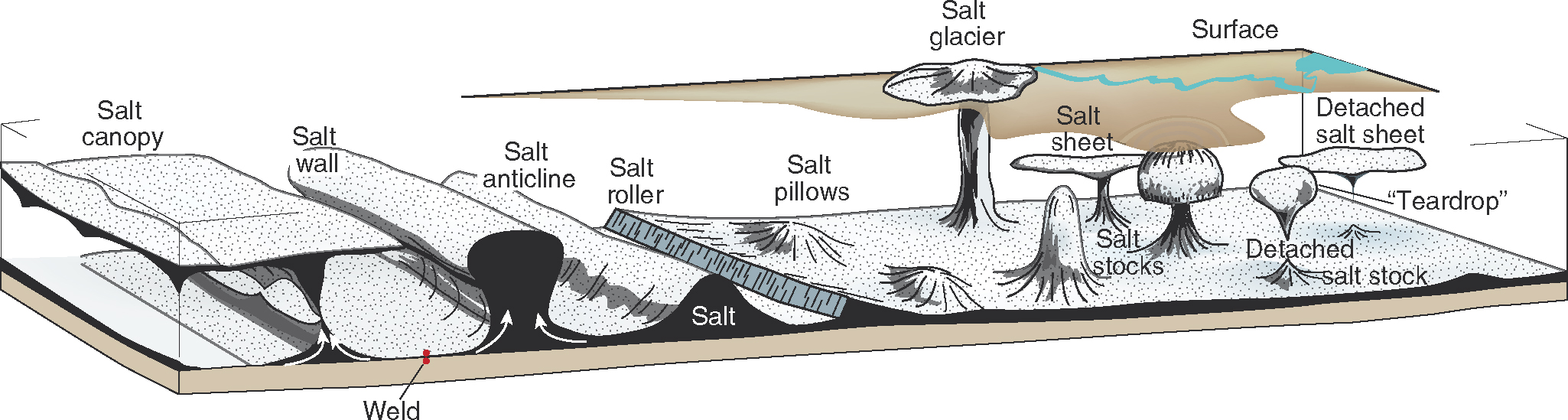
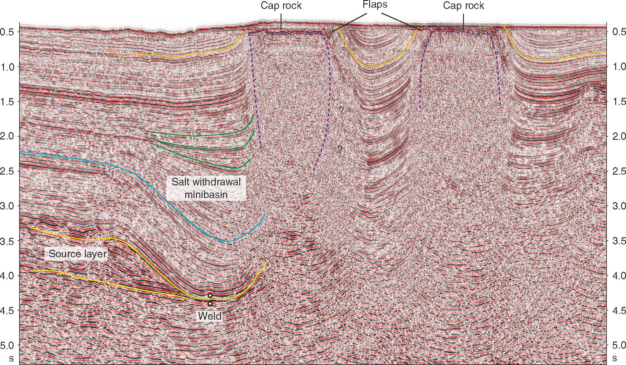
11. Explain the behavior of salt and the structures that result.
Salts have unique properties which allow them to form geological “plugs” for reservoirs. Layers of salts become buoyant and gravitationally unstable when buried in depths where the average density of the overburden exceeds that of the impure salt, 2.2 g/cm3. The depth of which the overburden material exceeds this threshold depends on the sediment type, porosity and compaction.
Salts deforms by viscous flow (acts like a fluid) even at the surface. The domineer deformation mechanisms are wet diffusion (presence of water) and dislocation creep. Dislocation creep is the formation, motion and destruction of linear defects in the crystal lattice while diffusion is about point defects, notably vacancies, and how they move through the crystal during deformation.
- Mechanically weak
- Low density (2.16 g/cm3)
- High heat conductivity
- Almost incompressible (fluid like)
- Impermeable forming very strong plugs
- Viscous (like a fluid)
- Causes board regions of deformation
- Enchances horizontal detachments
- Creates structural traps
12. Using several diagrams sketch the evolution of a metamorphic core complex.
Check 5 points questions above…
References
1) George H. Davis, Localization control for chlorite breccia deformation beneath Catalina detachment fault, Rincon Mountains, Tucson, Arizona, Journal of Structural Geology, Volume 50, May 2013, Pages 237-253, ISSN 0191-8141, 10.1016/j.jsg.2012.12.001. (http://www.sciencedirect.com/science/article/pii/S0191814112002726)
Keywords: Chlorite breccia; Ultramylonite; Mylonite; Detachment fault; Metamorphic core complex; Deformation localization
2) Structural Geology by Haakon Fossen
3) STRUCTURAL GEOLOGY OF ROCKS AND REGIONS: ISBN978-0-471-15231-6