In this YouTube CCNA tutorial, I use a real CCNA lab assignment from CCNA 1: Introduction to Networks curriculum. It is based on a Cisco Packet Tracer lab. You must create the lab Packet Tracer file for yourself based on a set of instructions provided to you by the CCNA administrators. The instructions are listed below the video. The commands used is listed below for your reference.
Video Tutorial
Lab Instructions
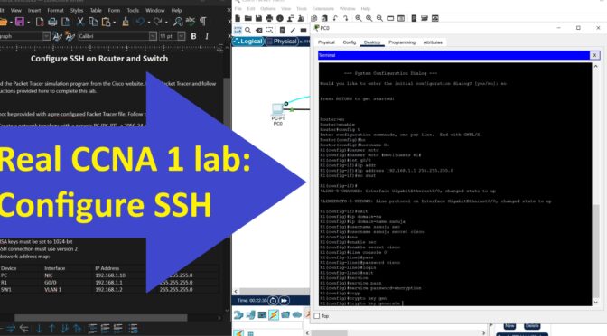
Configure SSH on Router and Switch
Part 1:
Download the Packet Tracer simulation program from the Cisco website. Install Packet Tracer and follow the instructions provided here to complete this lab.
Part 2:
You will not be provided with a pre-configured Packet Tracer file. Follow the instructions to:
1. Create a network topology with a generic PC (PC-PT), a 2950-24 switch and a 2911 router.
2. Connect the devices in this order: PC – Switch – Router, using appropriate cables. The router G0/0 interface should be connected to Switch Fe0/1 interface. The PC must be connected to Fe0/2 interface of the switch.
Part 3:
Configure the SSH on both the router and the switch using appropriate commands. You must also adhere to the following instructions:
1. The router hostname: R1
2. The switch hostname: SW1
3. Both the router and the switch must have a MOTD (Message Of The Day) that is meaningful
4. Use your first name as the domain name
5. All passwords must be cisco
6. All passwords must be encrypted
7. RSA keys must be set to 1024-bit
8. SSH connection must use version 2
9. Network address map:
Device Interface IP Address Mask
PC NIC 192.168.1.10 255.255.255.0
R1 G0/0 192.168.1.1 255.255.255.0
SW1 VLAN 1 192.168.1.2 255.255.255.0
Part 4:
You must be able to ping the R1 and SW1 from the PC. You must be able to connect to the R1 and SW1 using SSH.
Once the connections are confirmed, please save your Packet Tracer file and submit it to your instructor by uploading it to Cisco NetAcad lab assignment area.
Read the YT video description for supporting materials and link to documentation page for this lab.
Commands Used
PC 1 - Terminal

=====

Initial config diag: No

en <-privilege exec mode

config t <-global configuration mode


====hostname=====

hostname R1
====banner=====
banner motd #NetITGeeks R1#
====Interface config=====
int g0/0
ip addr 192.168.1.1 255.255.255.0
no shut
exit
=========
ip domain-name sanuja
username sanuja secret cisco
enable secret cisco
=========
line console 0
password cisco
login
exit
====to encrypt line console pass===
service password-encryption
==Generate RSA keys for SSH connection==
crypto key generate rsa
1024
ip ssh version 2
==Allow connections to router via virtual lines===
line vty 0 15
transport input ssh
login local
4. Setup the PC IP address
IP: 192.168.1.10
Subnet Mask: 255.255.255.0
Default Gateway: 192.168.1.1
5. Try pinging the router 192.168.1.1 using CMD - OK
6. ssh -1 sanuja 192.168.1.1
-----Password
en
config t
===========================================================
Switch
7. Connect the console cable between the PC0 and SW1
8. Configure the switch
en
config t
ho SW1
banner modt #NetITGeeks R2#
int vlan 1
ip add 192.168.1.2 255.255.255.0
no shut
enable secret cisco
line con 0
password cisco
exit
username sanuja secret cisco
service password-encryption
ip domain-name Sanuja
crypto key generate rsa
1024
ip ssh version 2
line vty 0 15
transport input ssh
login local
exit
ip default-gateway 192.168.1.1