Consumer Electronics Design not always beneficial if it retards the primary functions of a device. The internal antennas are such a design concept that causes a lot of headaches for tech guys like me. The primary function of an antenna is to transmit a signal, capture a signal or both. Since most modern equipment are manufactured with plastic casings (as opposed to metal), a lot of manufactures have opted for internal antennas. The advantage; now nothing is sticking out, they can make the equipment more desirable to mainstream consumers by making “beautiful” equipment boxes. I am on the other hand one of those people who would buy a device for its’ practical functionality overlooks.
The following modification was made on my VeraLite (Vera3 variant) to remove dead-zones in my Z-wave network. However, using the same principles and steps, you can also extend the range of your WiFi network. I will add bits of information specific to WiFi extension on this article.
Vera3 and VeraLite controllers
The door locks on Z-wave networks almost always accept only secure authenticated signals. In order to operate the locks, you must send the signal either directly from your Z-wave controller (in this case VeraLite) to the locks or use repeaters (or modules with secure repeaters) that are capable of secure signal handling. I found it is extremely hard to find such repeaters in Canada.
So I went with the second option; direct communication between the locks and the controller. However, my controller is in a locked cabinet far away from the locks. This causes reliability issues because unlike Z-wave light switches, door locks cannot take unsecured signals repeated from nearby low security switches.
Modification to the controller
Warning: This modification will void your manufactures’ warranty. Beware of the static charges. Static electricity could burn out your circuit board. Either use a grounded anti-static wrist strap or use extreme caution. Remove all power supply units (batteries & DC power unit) before opening the case.
Parts, tools and technical information
- Antenna must be able to handle frequency range of the device (for this mod, 908 MHz)
- U.fl/IPEX to RP-SMA Pigtail with at least 5 cm; 10 cm is too much; find happy medium) of wire length between the connection points
- GSM antenna extension cable (optional and longer the cable, more problems arises)
- Small needle-nose pliers
- Small Phillips screwdriver and a large slotted screwdriver or a flat plastic or metal piece
- Small electric drill or a utility knife
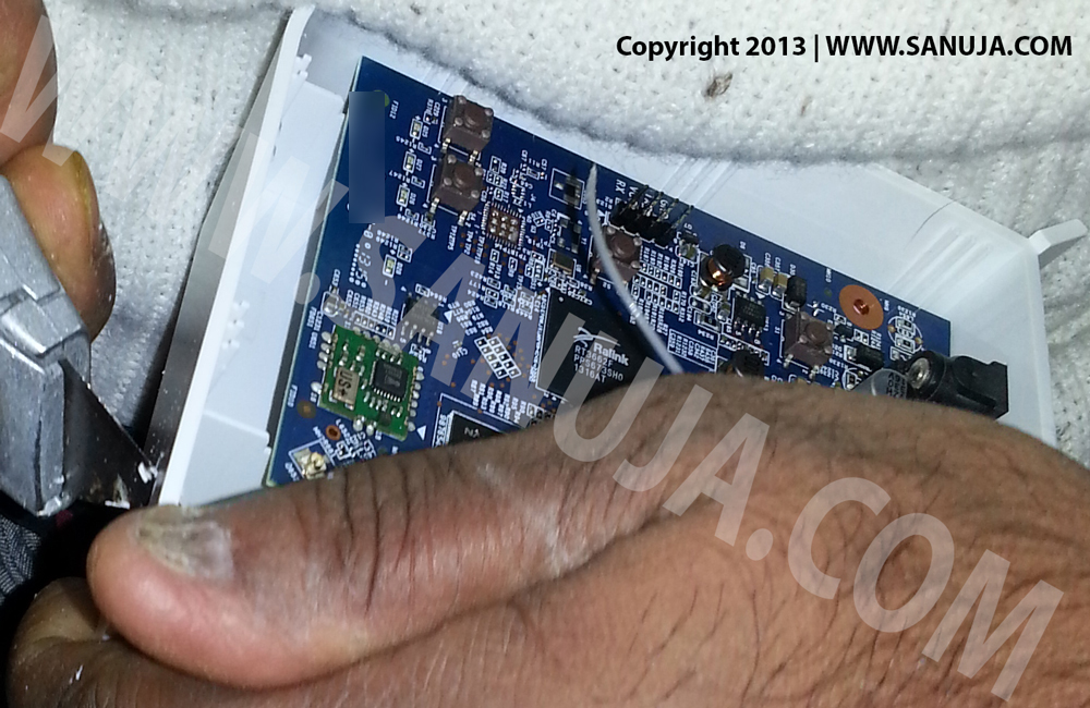
It is very easy to take apart VeraLite unit. Only two screws and few plastic clips that holds the plastic casing. One of my readers (“Jack”) pointed out that the screws will not come out from the casing. In that case, do not try to pull it out. Once the screws are loose, you do not have to take them out of the holes in order to separate the green cover from the case. Use a flat head screwdriver or a flat object to pull the cover apart. Be careful to not to break the clips that holding the two parts.
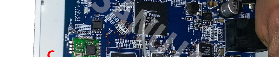
Inside you will find the internal antenna attached to side of the box with a connection wire going to the Printed Circuit Board (PCB). Click on the the image below for more detailed information.
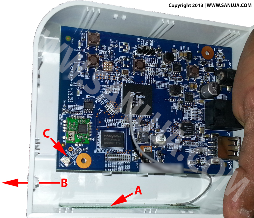
Disconnect the internal antenna wire from point C (refer to above image) by gently twisting and pulling on the connector. Do not pull from the wire because it will break the wire from the connector. I recommend using a small needle nose pliers.
Make a hole through the casing, either on the back or on the side. Make sure it is large enough to pass the SMA (SubMiniature version A) male connector but not its’ neck. I used a box cutter to be safe, but you can also use an electric drill. If you are using a large construction grade drill, please be careful to not to break the box. I found the utility knife to be the best option.
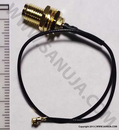
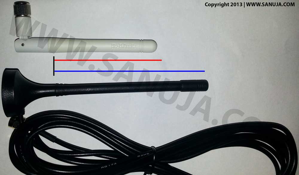
Take the U.fl/IPEX to RP-SMA Pigtail (Figure 3) and connect the U.fl side to the board. Then pass the SMA side from inside to outside. Then connect the other end to the point C (Figure 1) on the board.
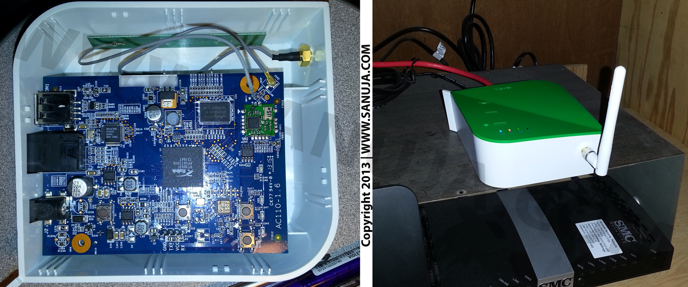
Put the box back together and your done! For the external antenna now you have the option of adding it directly to the device shown in Figure 3 or you can add a antenna cable before adding the antenna itself. This is what most people do when they want to secure their devices in a cabinet. You can keep the network controller inside while antenna outside for greater coverage.
It is quite possible to salvage antenna and U.fl/IPEX to RP-SMA Pigtail connection wire from old devices such as wireless routers and GSM devices. But unfortunately most WiFi routers are on 2.4 GHz band while Z-wave is in 900 MHz band. For example, this particular model is at 908 MHz frequency. If you cannot find a GSM device to get an antenna, please buy one (~ $8 – $12 CAD) to take the full advantage out of this modification. Connection wire from a WiFi router is suitable for Z-wave broadcast.
If you would like to know more about how antennas work, try this site.
Modify WiFi Routers
Yes, you can modify your b/g/n/ac WiFi routers with built-in antenna(s) by following the same instructions. The only difference is now you can use any old 2.4 GHz or 5 GHz (not very popular) antennas for your project.
One thought on “Modification to extend wireless range”
Comments are closed.