During home automation projects, you will probably replace the electrical fittings such as outlets for appliances and lighting fixtures. There are few basic things you should research before you begin. But first of all let me give you a warning; if you do not have experience working with electrical wring, please contact a professional for help. In this article, I will explain how to replace a traditional electrical switch to a Z-wave compatible switch.
Advice to all dummies
The following project involves working with ~ 110/240 volts alternating current (AC). Even with the power cut offed, there is always a risk of electric shock. Do not work on this project if; you are unfamiliar with electrical work, do not have proper equipments and/or regulations and laws in your area prohibit do-it-yourself (DIY) electrical modifications. I, Sanuja Senanayake or the site sanuja.com will not take any responsibility for any personal injury or property damage.
Equipment
The following items are essential to this project. In addition, you may require other materials such as drywall patches for cosmetic work.
- Suitable screw drivers and/or bits; electrically insulated drivers would be better
- Wire cutters and strippers
- Electrical tape
- Electrical wire connector clips in few different sizes
- Multimeter; a digital unit would be better/tester
- Z-wave compatible switch
Optional items.
- Extra electrical wires (short one would be enough)
- Gang box
- Wire staples and hammer
Let’s go…
After deciding which switch to replace, find the trip switch for the circuit on you central electrical box. If it is a light, I would turn it on to check if the power is still there. If you are installing a relay for a garage door, make sure the door is at closed position before you cut off the power. Prior to installing the Z-wave or wireless device read the manufacture’s guidelines for installation and usage. It is recommended to have at least 1/2 of the signal power from automation controller and the wireless LAN at the location. You may use a repeater for better signal strength. Please note, all Z-wave wired products (non-battery operated) are repeaters of the Z-wave signal.
After turning off the main power to the circuit, using your multimeter and/or tester, check if the power is out. Once you know that for sure, remove the two screws holding the switch. Gently, with some force, pull out the switch until you can access the left and right sides of the unit. Now, you should be able to remove the wires. But wait! Before you disconnect any wires from the old switch, I recommend taking a pictures of the setup. This can be very useful in places with three of more phases (and many other situations with lots of wires). It is important to have enough room in the gang box in order to accommodate the bulky back side of automated switches. If you find it is too tight to place all the new switches in the particular box, please replace the current gang box with a new unit with one extra slot. The extra slot can be closed up with a dummy plate as opposed to populating with an another switch.
You cannot install a dimmer switch in all locations due to wiring limitations. If you already have a traditional dimmer, you can install a automated dimmer at the same location. However, you may not have the dimming support on all gang boxes. The Z-wave switches often require a common wire. So, what is a common wire?
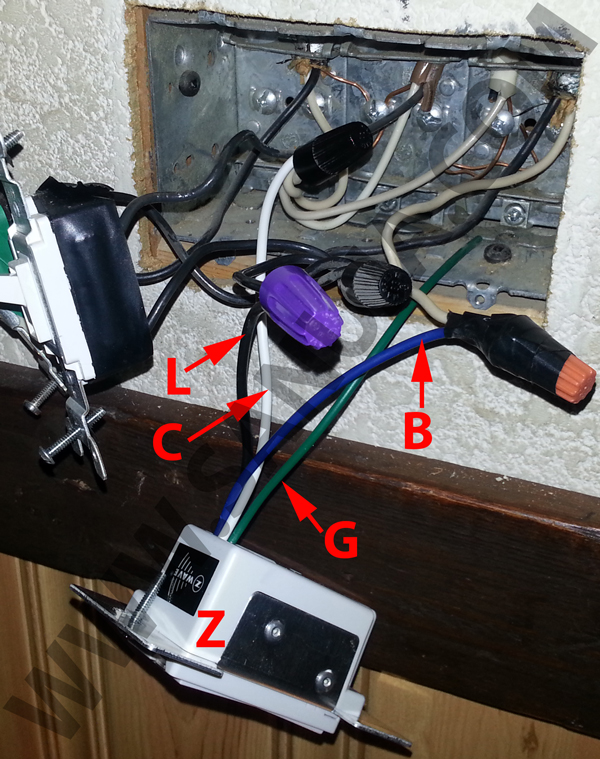
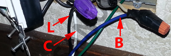
In the above image, the common wire is the white wire that is labeled C. All the common wires from switches attached to the same point. The wire B is the neutral wire (also white) that goes to the light. The green wire labeled G is the ground. Finally the Z-wave dimmer switch is labeled Z.
In this particular location, I can install two independent dimmers. But not all locations are wired to handle dimmers. If you do not currently have a dimming switch, it is possible that you cannot install one without extensive wiring. Unfortunately this is the case for most older houses. The cost of electrical home automation can be significantly increased with the age of the house.
When adding a new unit, always follow the instructions of the manufactures and the guidelines on electrical work in your area. Make sure the wattage rating of the automated unit does not exceed that of the load. For example, in my experience a unit that is rated for 500 W would be good for about 400 W load. After that between 400 – 500 W you are kind of experimenting. It may even handle 600 W but I recommend keeping units under load.
Make sure the wires are connected to each unit are securely held. Gently try to pull out the wires from all wire connector clips to ensure that all the wires are in place. Do not provide power to the circuit, without checking the integrity of your connections.
Once you have hooked up the wires, clear the area of any debris and keep the unit(s) out of the box. Please provide ample space between the electrical unit and the gang box to prevent electrical arcing. Now go to the main switch board and turn on the power. Check if the light(s) or appliance functions as expected. In case of a smoke or spark, immediately turn off the circuit.
Once you are done testing, turn off the circuit again. Now apply electrical tape to all exposed areas and wire connector clips. Put back the devices in the box and place the cover. Now you are ready to program the unit.
Cleaning things up
On the first image you can see I have applied electrical tape to cover all exposed connectors and wires. It is important to use the tapes to isolate these connectors to prevent shorting.
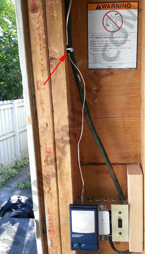
On the image bellow, the arrow in the above image is pointing to a staple which holds the wires in place. You can also see a Z-wave relay switch and the garage door opener switch. I have replaced the entire gang box with a new one. As you can see the metal box has been secured on both sides.
Programming an Z-wave switch
There are several companies manufacture Z-wave compatible switches. GE and Evolve and Leviton are few popular companies. Regardless of the manufacture, the process is simple. Press the add button on your Z-wave controller near the switch. Then press the switch at ON position several times until your Z-wave controller indicate successful addition. Each Z-wave controllers have their own set of instructions on how this works. Please follow the guidelines accordingly. For your information; I am very satisfied with the options and possibilities of VeraLite3 controller. However, I am cannot recommended anything since each controller comes with different advantages.
Other programing options
Electrical installation process is same for all units. The x10 and INSTEON controllers will have sightly different programming steps. At the end of the day, this article is all about basics of home electrical wiring. Refer to your manufacture’s user guide on how to add items to your specific programming standards.