All Engineering and Geology students should be able to understand and construct of Mohr Circles or Mohr diagrams by hand. Most companies use computer software to draw Mohr circles. However, it is important as a scientist for you to be able to do them manually. Indeed manual drawings are very useful in field work environments where you may have limited access to more sophisticated technologies. This is a guide was written specifically for the University of Calgary structural geology classes. However, the general scientific ideas behind Mohr circles will remain the same regardless of the application. I tried to make this article as simple as possible, so the general users can also benefit from it.
Important concepts:
1) We are not interested in the maximum and minimum components of the normal stress. Secondary forces have either no or minimal impact on the geologic volume.
2) By convention, normal stress is on the x-axis, shear stress is on the y-axis and generally accepted units for the Mohr Circle is megapascals (MPa).
3) When working with multi-step problems, always make the MPa spacing on both x and y axis about twice as large as it needs to be; this will ensure enough room for data manipulation.
4) On plane diagrams;
Normal stress (principle stress): sigma-1 and sigma-3
Compression +
Stretching –
Shear stress
Right Lateral (Dextral) –
Left Lateral (Sinistral) +
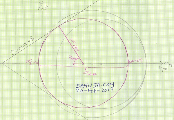
How to plot a Mohr Circle
A Mohr Circle is a graphical representation of pressure on a given geologic unit or structural feature. It could be a geologic material like a rock, a structural feature like a fracture or it could be a man-made structure like a bridge. Mohr circles are used to quantify the strength of materials under given pressures.
Step 1: Find the most extreme values of stresses given in the problem and construct the graph parameters accordingly.
Step 2: Each point should have normal and a shear component points (if one of them is zero, plot it on the axis).
Step 3: Now there will be two extreme points which govern the diameter of the circle. Find the midway point between them and draw a circle using a protector.
Step 4: If a condition (typically an equation) is given for the failure envelope, find the x and y intercept and draw two lines; one with the positive slope and the other with the negative slope (the absolute value of the slopes should be same!)
Step 5: If a change in condition for σ-1 (“seigma-1”) and/or σ-3 is provided, do not erase the original Mohr Circle. But draw a new one with the new information provided.
How to use the Mohr Circle
Differential Stress:
![]()
Deviatoric Stress:![]()
Mean Stress:![]()
Maximum/Minimum Principle Stress: (aka Normal Stress) The maximum is the most right x-intersection point of the Mohr Circle. The minimum is the most left x-intersection point of the Mohr Circle.
Maximum/Minimum Shear Stress: The maximum is the most highest point (doesn’t have to be the intersection) of the Mohr Circle. The minimum is the most lowest (doesn’t have to be the intersection) point of the Mohr Circle.
Maximum angle of force:
Failure envelope:![]()
Other useful equations:
Example Question
Edited by: Nicholas Coffey, Chief Scientist, Coffey Geoscience, Salem OR
Updated: 26-Sept-2016
One thought on “Basic construction of a Mohr Circle”
Comments are closed.